



Microwave (MW) Link Down – Complete Troubleshooting Guide
Introduction
Microwave (MW) communication is one of the most widely used transmission technologies in modern telecommunications networks. It provides high-capacity, point-to-point wireless connectivity between cellular base stations, network aggregation sites, internet service providers, enterprise campuses, utility networks, and remote communication facilities. Microwave links are especially valuable in areas where fiber-optic deployment is difficult, expensive, or impractical due to mountains, rivers, forests, deserts, or other geographical obstacles.
A microwave link consists of two radio terminals communicating through a highly directional microwave signal transmitted over free space. When operating correctly, microwave links provide reliable, low-latency communication capable of transporting voice, video, data, and internet traffic. However, environmental conditions, equipment failures, configuration errors, and other factors can cause a microwave link to fail.
A Microwave Link Down alarm indicates that communication between the local and remote microwave terminals has been interrupted. Diagnosing the problem requires a systematic troubleshooting approach that examines power, alarms, signal levels, hardware, software, radio configuration, and environmental conditions.
Typical Microwave Link Structure
A standard microwave communication system consists of the following components:
IDU (Indoor Unit) → IF Cable → ODU (Outdoor Unit) → Microwave Signal Through Air → Remote ODU → IF Cable → Remote IDU
Each component has a specific function.
Indoor Unit (IDU)
The Indoor Unit performs digital signal processing and network interfacing. It connects directly to routers, switches, multiplexers, or base station equipment. Functions include:
- Traffic processing
- Modulation and demodulation
- Alarm monitoring
- Network management
- Synchronization
- Performance monitoring
IF Cable
The Intermediate Frequency (IF) cable carries signals and DC power between the IDU and the ODU.
A damaged IF cable is one of the most common causes of microwave failures.
Outdoor Unit (ODU)
The Outdoor Unit performs RF transmission and reception.
Major functions include:
- Frequency conversion
- RF amplification
- Microwave transmission
- Microwave reception
The ODU connects directly to the microwave antenna.
Microwave Antenna
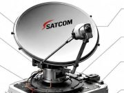
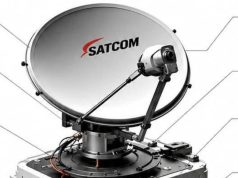
Usually a parabolic dish antenna, it focuses RF energy into a narrow beam directed toward the remote station.
Common Microwave Link Alarms
Modern microwave radios continuously monitor equipment status and generate alarms whenever abnormal conditions occur.
The most common alarms include:
LOS (Loss of Signal)
The receiver cannot detect a usable RF signal.
Possible causes include:
- Antenna misalignment
- ODU failure
- IF cable damage
- Severe weather
- Power failure
LOF (Loss of Frame)
The receiver detects RF energy but cannot properly decode the digital frame structure.
This usually indicates poor signal quality or synchronization problems.
RSL LOW
Received Signal Level (RSL) has fallen below the normal operating threshold.
A low RSL may result from:
- Rain fade
- Alignment problems
- Obstructions
- Cable losses
High BER
BER stands for Bit Error Rate.
High BER indicates excessive transmission errors caused by:
- Weak signal
- Interference
- Poor modulation quality
- Hardware faults
Link Down
The microwave connection has completely failed.
Traffic cannot pass between the two terminals.
No Far End
The local radio cannot communicate with the remote microwave terminal.
RF Muted
The transmitter has automatically disabled RF transmission due to protection mechanisms or configuration issues.
ODU Not Connected
The Indoor Unit cannot detect communication with the Outdoor Unit.
Root Causes of Microwave Link Down
1. Weather Effects (Rain Fade)
Heavy rainfall is one of the leading causes of microwave outages.
Rain droplets absorb and scatter microwave energy.
Higher-frequency links such as:
- 18 GHz
- 23 GHz
- 38 GHz
are much more susceptible than lower-frequency systems.
Typical effects include:
- Reduced RSL
- Increased BER
- Adaptive modulation fallback
- Temporary link outage
Most rain-induced outages disappear once weather conditions improve.
2. Antenna Misalignment
Microwave antennas require extremely precise alignment.
Strong winds, earthquakes, vibration, loose mounting brackets, or accidental impact can shift antenna direction by only a fraction of a degree, yet significantly reduce received signal strength.
Symptoms include:
- Sudden RSL decrease
- Unstable communication
- Link flapping
- High BER
Realignment using the received signal level is often required.
3. Power Failure
Microwave systems depend on reliable DC power supplies.
Potential power-related problems include:
- AC mains failure
- Rectifier failure
- Battery failure
- Blown fuse
- DC breaker trip
- Damaged power cable
Without DC power, the IDU or ODU shuts down completely, causing total communication loss.
4. Hardware Failure
Equipment failure can occur in any microwave component.
Common failures include:
- Defective ODU
- Failed power amplifier
- Receiver failure
- Faulty modem
- Damaged IDU interface card
- Failed Ethernet port
- Defective SFP module
Hardware faults often require replacement of the affected module.
5. IF or RF Cable Problems
The IF cable carries both communication signals and DC power.
Possible problems include:
- Loose connectors
- Broken cable
- Water ingress
- Corrosion
- Incorrect connector installation
Cable faults frequently produce intermittent communication problems.
6. Radio Frequency Interference
Microwave interference occurs when another transmitter operates on the same or an adjacent frequency.
Interference sources include:
- Nearby microwave links
- Unauthorized transmitters
- Radar systems
- External RF equipment
Symptoms include:
- High BER
- Reduced throughput
- Link instability
- Adaptive modulation switching
Spectrum analysis helps identify interference.
7. Configuration Mismatch
Both microwave radios must use matching configuration parameters.
Common mismatches include:
- Incorrect transmit frequency
- Incorrect receive frequency
- Wrong polarization
- Different channel bandwidth
- Different modulation settings
- Wrong Link ID
- Incorrect XPIC configuration
Configuration mismatches prevent successful communication even when RF signal strength is adequate.
8. Blocked Line of Sight
Microwave signals require an unobstructed line of sight.
Possible obstructions include:
- New buildings
- Growing trees
- Construction cranes
- Billboards
- Hills
- Towers
Obstructions entering the Fresnel zone reduce signal strength significantly.
9. Software Issues
Occasionally, microwave equipment experiences software-related failures.
Examples include:
- Firmware bugs
- Memory overflow
- Process crashes
- Operating system lockup
Symptoms may include frozen communication despite normal hardware operation.
Software upgrades often resolve these problems.
10. Poor Link Design
Some microwave failures originate during system design.
Examples include:
- Excessive link distance
- Inadequate fade margin
- Small antenna diameter
- Low transmit power
- No redundancy
- Incorrect frequency planning
Links designed with minimal safety margins are more likely to fail during adverse weather.
Step-by-Step Troubleshooting Procedure
Step 1: Verify Power
Confirm that:
- IDU is powered ON.
- ODU receives approximately –48 V DC.
- Rectifier is operating normally.
- Batteries are healthy.
Power alarms should be cleared before continuing.
Step 2: Review Active Alarms
Access the microwave management system and examine all active alarms.
Focus on:
- LOS
- LOF
- Link Down
- High BER
- ODU Disconnected
- No Far End
Alarm history often identifies the original fault.
Step 3: Check Received Signal Level (RSL)
Typical microwave systems operate with RSL values between approximately –30 dBm and –50 dBm, depending on the equipment and link design.
If RSL has dropped significantly:
Possible causes include:
- Rain fade
- Antenna movement
- Cable damage
- ODU failure
Step 4: Evaluate Weather Conditions
Check current weather conditions.
Heavy rain or severe storms frequently cause temporary microwave degradation.
Monitor:
- RSL trend
- BER
- Modulation level
If rain is responsible, normal operation often resumes automatically.
Step 5: Verify the Remote Site
Determine whether the far-end site is operational.
Check:
- Network Management System (NMS)
- Ping response
- Remote alarms
- Power availability
If the remote site is offline, communication cannot be restored until it is repaired.
Step 6: Inspect IF Cables
Physically examine:
- Cable routing
- Connector tightness
- Water ingress
- Corrosion
- Mechanical damage
Replace damaged cables when necessary.
Step 7: Verify Antenna Alignment
Measure RSL while adjusting antenna direction.
Optimization involves:
- Azimuth adjustment
- Elevation adjustment
Secure all mounting bolts after alignment.
Step 8: Compare Configuration
Verify identical settings at both ends.
Check:
- Frequency
- Polarization
- Channel bandwidth
- Modulation
- Link ID
- XPIC parameters
Even minor configuration differences can prevent link establishment.
Step 9: Investigate Interference
Use spectrum analysis to identify unwanted RF signals.
Possible corrective actions include:
- Frequency reassignment
- Antenna repositioning
- Improved shielding
- Regulatory coordination
Step 10: Restart Equipment
If hardware and configuration appear correct:
- Restart IDU.
- Restart ODU.
- Confirm synchronization.
Rebooting often clears temporary software faults.
Quick Field Diagnosis
Experienced field engineers often identify likely faults from symptoms alone.
No Power
Possible causes:
- Rectifier failure
- Battery problem
- DC breaker trip
RSL Extremely Low or Zero
Likely causes:
- Antenna misalignment
- ODU failure
- IF cable damage
High BER
Likely causes:
- RF interference
- Rain fade
- Weak signal
No Far End
Likely causes:
- Remote site power failure
- Frequency mismatch
- Polarization mismatch
Link Flapping
Likely causes:
- Interference
- Loose antenna
- Marginal fade margin
Best Practices for Reliable Microwave Links
Preventive maintenance greatly reduces microwave outages.
Recommended practices include:
- Maintain precise antenna alignment.
- Use high-quality IF and RF cables.
- Protect connectors from moisture.
- Inspect tower hardware regularly.
- Ensure clear line of sight and Fresnel zone clearance.
- Monitor RSL and BER continuously.
- Maintain adequate fade margin during link design.
- Install lightning protection and proper grounding.
- Upgrade firmware when recommended by the manufacturer.
- Use protected configurations such as 1+1 or ring topologies for critical links.
- Schedule periodic preventive maintenance and performance testing.
Conclusion
A Microwave Link Down condition is one of the most critical alarms in a telecommunications transmission network because it interrupts the flow of voice, data, and internet traffic between network sites. Effective troubleshooting requires a systematic approach that begins with verifying power to the Indoor Unit (IDU) and Outdoor Unit (ODU), followed by analyzing alarms, checking the Received Signal Level (RSL), inspecting IF cables, confirming antenna alignment, reviewing configuration parameters, and investigating weather conditions or radio-frequency interference. Common causes include rain fade, hardware faults, power failures, blocked line of sight, configuration mismatches, software issues, and poor link design. By following a structured troubleshooting process and adopting preventive maintenance practices—such as maintaining proper alignment, ensuring adequate fade margin, protecting equipment from lightning, and using redundant configurations where appropriate—engineers can maximize microwave link reliability, minimize downtime, and ensure uninterrupted telecommunications services for users and network operators alike.



https://shorturl.fm/72tqd