

Huawei RTN ODU Configuration and Link Analysis
Introduction
Huawei RTN microwave transmission systems are widely used by mobile network operators, internet service providers, utilities, and enterprise networks to provide reliable point-to-point wireless communication. One of the most critical components of an RTN microwave link is the Outdoor Unit (ODU), which is responsible for transmitting and receiving microwave radio signals between two sites. Proper ODU configuration is essential to ensure stable communication, high throughput, and reliable network performance.
The Huawei Web Local Craft Terminal (Web LCT) provides engineers with an intuitive interface for configuring, monitoring, and troubleshooting RTN microwave equipment. Through Web LCT, engineers can view equipment information, monitor alarms, analyze received signal levels, configure frequencies, adjust modulation parameters, and diagnose communication problems.
The configuration report presented here describes a Huawei RTN microwave link that is experiencing communication problems with the opposite terminal. Although the received signal strength appears acceptable, the system indicates that communication between the local and remote ODUs has failed. Understanding each configuration parameter helps field engineers quickly identify the root cause and restore normal operation.
Software Information
The microwave radio is managed using the Huawei Web LCT software, which is the standard local maintenance interface for Huawei RTN equipment. Web LCT enables engineers to perform both basic and advanced configuration tasks without requiring direct access to the network management system.
The Network Element (NE) information is as follows:
- NE ID: 187-30461
- IP Address: 129.9.118.253
- Current User: root
- NE Status: RUNNING
- Software Version: 5.95.24.23
The NE status of RUNNING confirms that the local microwave node is powered on and operating normally. The software version identifies the firmware currently installed on the equipment, which is important when checking compatibility between the local and remote sites or when applying software upgrades and patches.
Board Information
The selected hardware board is:
- 3-ISM8-1 (RTNIF-1)
This interface board provides communication between the indoor unit and the outdoor radio equipment.
The selected Outdoor Unit is:
- 23-ODU
The ODU performs several important functions, including:
- Microwave transmission
- Microwave reception
- Frequency conversion
- RF signal amplification
- Automatic transmit power control
- Signal filtering
The ODU is mounted close to the antenna to minimize feeder losses and improve transmission efficiency.
Link Status Analysis
One of the most important sections of the configuration report is the current microwave link status.
Measured parameters are:
- Received Signal Level (RSL): -47.9 dBm
- Transmit Signal Level (TSL): 9.8 dBm
The received signal level represents the power of the incoming microwave signal from the remote station.
An RSL of approximately −48 dBm is generally considered a healthy signal for many Huawei microwave systems and indicates that sufficient RF energy is reaching the receiver.
Despite the acceptable signal level, the equipment displays the following warning:
“No contact with opposite terminal.”
This alarm indicates that although radio energy is being received, the local ODU cannot establish proper communication with the remote ODU. In other words, the radio carrier is present, but the digital communication required to establish the microwave link has failed.
Possible Causes of Opposite Terminal Communication Failure
Several conditions can produce this alarm.
Far-End Equipment Power Failure
The remote microwave equipment may be switched off due to:
- AC power failure
- DC power failure
- Rectifier fault
- Battery depletion
- Maintenance shutdown
If the far-end ODU is not powered correctly, communication cannot be established.
Frequency Mismatch
Both microwave radios must use exactly matching transmit and receive frequencies.
For example:
Local TX Frequency = Remote RX Frequency
Local RX Frequency = Remote TX Frequency
Any incorrect frequency assignment prevents synchronization between the two radios.
Polarization Mismatch
Microwave antennas normally use either:
- Horizontal (H)
- Vertical (V)
If one site uses horizontal polarization while the other uses vertical polarization, communication will fail even if the signal level appears adequate.
Antenna Misalignment
Strong winds, tower movement, improper installation, or mechanical damage may cause the antenna to become misaligned.
Even a small angular deviation can reduce link quality or prevent communication entirely.
IF Cable Problems
The Intermediate Frequency (IF) cable connects the indoor unit to the outdoor unit.
Potential cable faults include:
- Loose connectors
- Water ingress
- Cable damage
- Incorrect cable length
- Connector corrosion
These faults can interrupt communication between the indoor and outdoor equipment.
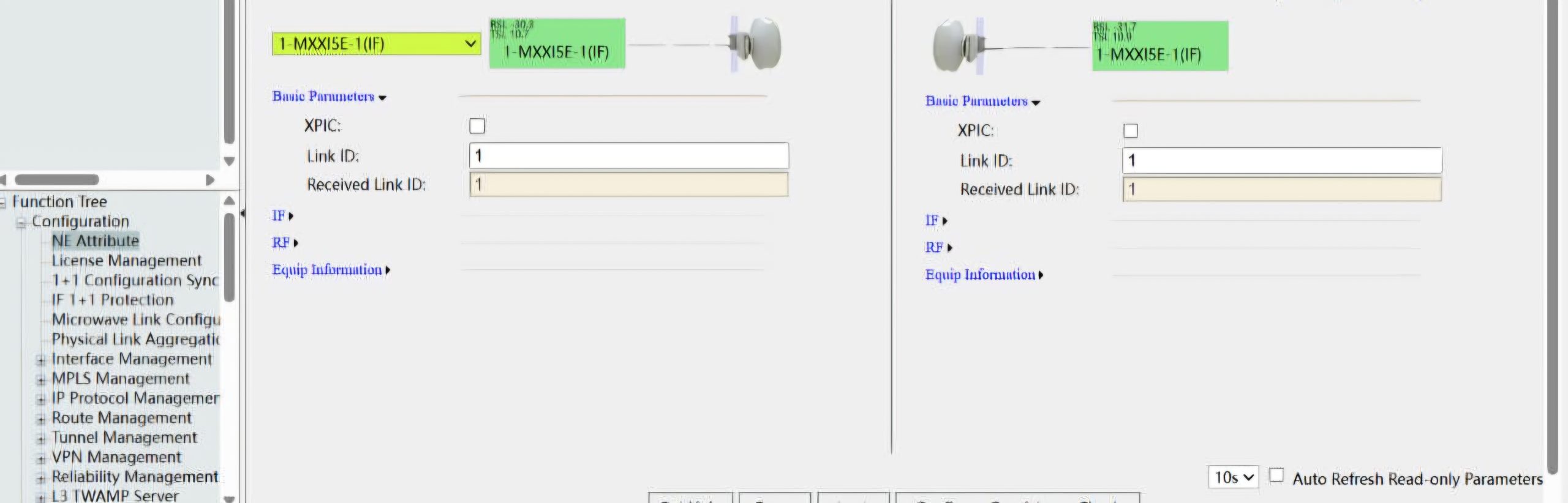
Incorrect Link ID
The report shows:
- Configured Link ID = 1
- Received Link ID = 1
Since both values match, the Link ID appears to be correctly configured.
Hardware Failure
Possible hardware failures include:
- Defective ODU
- Damaged RF amplifier
- Failed modem
- Faulty interface board
- Defective antenna coupler
Hardware faults should only be investigated after configuration issues have been eliminated.
Protection Configuration
The microwave system is configured as:
- Protection Mode: 1+0
- XPIC: Disabled
A 1+0 configuration means that the microwave link uses a single radio path with no backup radio.
Advantages include:
- Lower equipment cost
- Simpler installation
- Reduced power consumption
However, because there is no redundant radio path, any equipment failure immediately interrupts communication.
XPIC (Cross Polarization Interference Cancellation) is disabled.
XPIC is normally used in high-capacity microwave links to transmit two independent data streams using horizontal and vertical polarization simultaneously.
Because XPIC is disabled, the link operates using only one polarization channel.
Interface Configuration
The IF service type is configured as:
Hybrid (Native E1 + Ethernet)
This means the microwave system supports both:
- Ethernet traffic
- Traditional E1 digital circuits
Hybrid operation allows legacy telecommunications services and modern packet-based services to coexist on the same microwave link.
The configured channel bandwidth is:
28 MHz
Channel bandwidth determines the maximum data rate that the microwave radio can support.
Larger bandwidth generally provides higher capacity but requires additional licensed spectrum.
Adaptive Modulation
Adaptive Modulation (AM) is enabled.
Adaptive Modulation automatically changes the modulation scheme depending on radio link quality.
The report indicates:
- Guaranteed Capacity:
- QPSK
- 43 Mbit/s
- Maximum Capacity:
- 2048QAM
- 242 Mbit/s
Current modulation:
QPSK
This indicates that the microwave radio has automatically reduced its modulation level.
Under normal conditions, the system would use much higher modulation such as:
- 64QAM
- 128QAM
- 256QAM
- 512QAM
- 1024QAM
- 2048QAM
Higher modulation provides significantly greater throughput.
However, higher modulation also requires:
- Better signal quality
- Higher signal-to-noise ratio
- Better antenna alignment
Because the current modulation is only QPSK, the system is operating in its most robust but lowest-capacity mode.
This usually indicates degraded microwave link quality.
RSL Analysis
The measured received signal level is:
−47.9 dBm
For many Huawei microwave systems, this value is considered acceptable.
Normally, such an RSL would support higher modulation levels.
Therefore, the acceptable RSL combined with the loss of communication suggests that the problem is not simply weak signal strength.
Instead, the fault is more likely associated with:
- Incorrect configuration
- Frequency mismatch
- ODU synchronization failure
- Remote equipment failure
- IF communication problem
Alarm Summary
The microwave node reports multiple active alarms:
- Red Alarms: 4
- Yellow Alarms: 7
- Minor Alarms: 2
Red alarms usually represent critical failures requiring immediate attention.
Yellow alarms indicate warning conditions that may affect service.
Minor alarms indicate less severe conditions that should still be investigated.
The presence of multiple alarms suggests that the communication failure may be causing several secondary alarms throughout the microwave node.
Reviewing detailed alarm logs in Web LCT can help identify the first alarm that occurred, making root-cause analysis easier.
Function Tree
The Web LCT interface provides access to several important management functions.
Configuration menu includes:
- ODU Interface
- Performance Graph Analysis
Performance monitoring allows engineers to examine:
- Signal level trends
- Error rates
- Throughput
- Modulation history
- Temperature
- RF output power
Historical graphs are particularly useful for identifying intermittent faults caused by weather, tower movement, or equipment instability.
Field Engineer Troubleshooting Checklist
A systematic troubleshooting procedure should be followed.
Step 1: Verify power availability at the far-end site.
Step 2: Confirm transmit and receive frequencies on both microwave radios.
Step 3: Verify antenna polarization.
Step 4: Inspect antenna alignment using alignment tools or spectrum analysis.
Step 5: Check IF cable continuity and connector condition.
Step 6: Review ODU alarm history using Web LCT.
Step 7: Ping the remote Network Element if network connectivity exists.
Step 8: Compare configuration settings at both sites.
Step 9: Verify XPIC configuration if dual-polarization transmission is expected.
Step 10: Confirm licensed frequency assignments and ensure the configured frequencies match the approved spectrum plan.
Following these steps in sequence minimizes troubleshooting time and helps isolate the fault efficiently.
Most Likely Root Cause
Based on the available information, the most probable problem is a failure in communication between the local and remote microwave terminals.
Although the received signal level is good, the inability to establish contact with the opposite terminal suggests one or more of the following:
- Incorrect transmit or receive frequency configuration
- Remote site power failure
- Antenna alignment error
- Polarization mismatch
- IF cable fault
- ODU synchronization failure
- Hardware malfunction in the local or remote ODU
Because the Link ID values match and the received signal strength is acceptable, configuration mismatch or remote equipment failure becomes more likely than poor signal strength alone.
Conclusion
The Huawei RTN ODU configuration demonstrates that the local microwave equipment is operational and receiving an adequate RF signal; however, communication with the opposite terminal has not been established. The 1+0 protection configuration, Hybrid E1 and Ethernet interface, 28 MHz channel bandwidth, and adaptive modulation settings indicate a standard point-to-point microwave installation. Although the measured RSL of −47.9 dBm is within an acceptable operating range, the system has fallen back to QPSK modulation, indicating degraded link performance. Combined with multiple active alarms and the “No contact with opposite terminal” message, this points toward a configuration mismatch, remote equipment failure, antenna alignment problem, or hardware fault. A structured troubleshooting process involving verification of power, frequency, polarization, IF cabling, alarm logs, and configuration consistency on both ends of the link is essential to restore reliable microwave communication and return the system to full-capacity operation.