

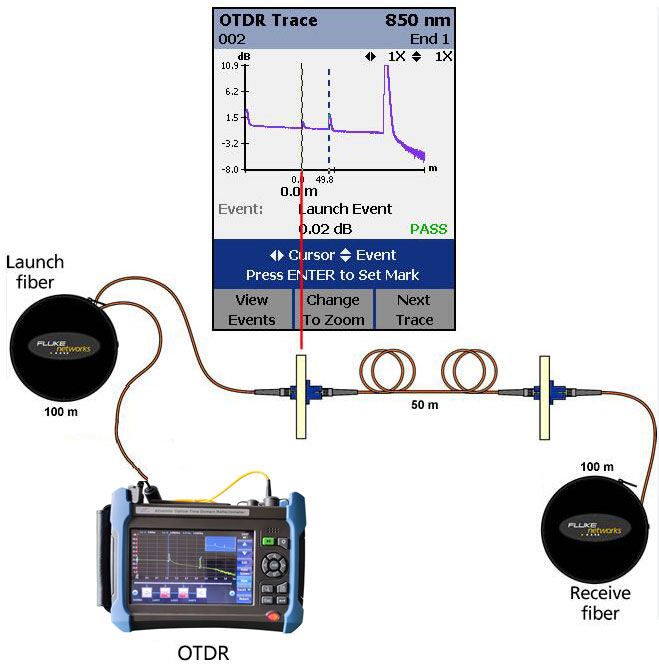
OTDR stands for Optical Time-Domain Reflectometer. It is a specialized test instrument used to evaluate, troubleshoot, characterize, and maintain fiber-optic cables and networks. OTDR testing is one of the most important activities in fiber-optic installation and maintenance because it allows technicians to determine the condition of a fiber link without physically opening the entire cable route.
Unlike a conventional optical power meter, which mainly measures the amount of optical power received at the end of a fiber, an OTDR can provide information about where losses, reflections, splices, connectors, bends, breaks, and other events occur along the fiber. It does this by sending a short pulse of light into the optical fiber and analyzing the light that is returned through a phenomenon known as backscattering.
1. Basic Principle of an OTDR
The operation of an OTDR is based on the principle of Rayleigh backscattering. When an optical pulse travels through a fiber, a small portion of the light is naturally scattered in different directions because of microscopic variations in the glass. Some of this scattered light travels backward toward the OTDR.
The instrument measures this returned light as a function of time. Since the speed of light in the fiber is known, the OTDR can calculate the approximate distance to the point from which the reflected or backscattered signal originated.
In simple terms, the process is:
OTDR → sends optical pulse → fiber → light is scattered/reflected → OTDR receives returned light → instrument calculates distance and loss.
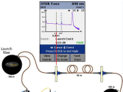
The OTDR then displays the results as a graph called an OTDR trace or reflectogram. The horizontal axis normally represents distance, while the vertical axis represents the optical signal level, usually expressed in dB.
For example, if an OTDR detects a strong reflection at approximately 2.5 km, this may indicate a connector, mechanical splice, or another reflective event at that distance. If the signal suddenly disappears at 5 km, the fiber may have a serious fault or complete break at approximately that location.
2. Major Functions of an OTDR
An OTDR provides several important functions in fiber-optic networks.
Measuring Fiber Length
One of the simplest functions of an OTDR is determining the length of an optical fiber. By measuring the time taken for the optical pulse to travel to a particular point and return, the instrument can estimate the distance.
The calculation is related to:
Distance = (Speed of light × Time) / (2 × Refractive Index)
The division by two is necessary because the optical signal travels from the OTDR to the event and then the returned signal travels back to the OTDR.
Measuring Fiber Attenuation
Fiber attenuation describes the reduction of optical power as light travels through the fiber. It is normally expressed in dB/km.
For example, if a fiber has an attenuation of 0.35 dB/km, the optical power gradually decreases as the transmission distance increases.
An OTDR can calculate the attenuation of different sections of fiber and help technicians determine whether the fiber is performing within the expected specification.
Locating Fiber Breaks
One of the most useful applications of an OTDR is locating a fiber cut or break.
When a fiber is completely broken, the OTDR trace normally shows a significant event followed by the end of the fiber. The displayed distance allows the technician to identify approximately where the physical fault has occurred.
For example, if the OTDR shows the end of the fiber at 8.72 km, technicians can investigate the cable route around that distance instead of checking the entire network.
Detecting Connectors
Connectors can introduce both insertion loss and reflection into a fiber-optic system. OTDRs can identify connector events because they often produce a noticeable reflective peak on the trace.
Common fiber connectors include SC, LC, FC, and ST types.
Poorly cleaned, damaged, or incorrectly installed connectors may produce excessive loss or reflection.
Testing Splices
Fiber-optic cables are frequently joined using fusion splicing or mechanical splicing.
A good fusion splice should introduce very little loss. An OTDR can identify the splice location and estimate the splice loss.
For example, if an OTDR identifies a splice at 4.2 km with an estimated loss of 0.08 dB, the technician can determine whether the splice meets the required project specification.
3. OTDR Trace
The OTDR trace is one of the most important outputs of an OTDR test.
A typical trace contains several events. These may include:
- Launch connector
- Fiber section
- Fusion splice
- Mechanical splice
- Connector
- Optical splitter
- Macro-bend
- Fiber end
- Fiber break
- Reflective event
The technician must learn how to interpret these events correctly.
A normal fiber section generally appears as a gradually declining line because optical power decreases as the signal travels through the fiber.
A splice may appear as a small downward step, while a reflective connector may appear as a sharp peak followed by a decrease in signal level.
4. Important OTDR Parameters
Several parameters are important when configuring an OTDR.
Wavelength
Common OTDR wavelengths include:
850 nm, 1300 nm, 1310 nm, 1490 nm, 1550 nm, and 1625 nm.
The wavelength selected depends on the type of fiber and the application.
For example, 1310 nm and 1550 nm are commonly used when testing single-mode fiber in telecommunications networks.
The 1550 nm wavelength is particularly useful for identifying certain fiber bends because bending losses can become more significant at longer wavelengths.
Pulse Width
The OTDR sends optical pulses into the fiber. The pulse width affects both measurement range and resolution.
A short pulse generally provides better event resolution but has less measurement range.
A long pulse can reach farther distances but may reduce the ability to distinguish between events that are very close together.
Therefore, selecting the correct pulse width is important.
Range
The range determines the approximate maximum distance that the OTDR will analyze.
For example, if testing a 10 km fiber link, an appropriate range might be selected around 20 km or another suitable value depending on the instrument and test requirements.
Selecting an unnecessarily large range can reduce measurement efficiency and resolution.
Refractive Index
The Index of Refraction (IOR) is another important OTDR parameter.
The instrument uses the refractive index to calculate distance from the measured travel time of the optical signal.
An incorrect IOR can result in inaccurate distance measurements. Therefore, technicians should use the correct fiber manufacturer’s value whenever possible.
Averaging Time
OTDR measurements can be affected by noise. Averaging allows the instrument to take multiple measurements and combine them to produce a cleaner trace.
Longer averaging times generally improve measurement quality but increase the time required for testing.
5. Dead Zones
An important characteristic of an OTDR is its dead zone.
A dead zone is a distance immediately following a strong reflective event during which the OTDR may have difficulty accurately measuring another event.
There are two commonly discussed types:
- Event dead zone
- Attenuation dead zone
A strong reflection, such as a connector close to the OTDR, can temporarily saturate the receiver. During this period, the instrument may not be able to accurately distinguish nearby events.
This is why technicians commonly use a launch fiber and sometimes a receive fiber when performing professional OTDR tests.
6. Launch and Receive Fibers
A launch fiber is a length of fiber connected between the OTDR and the fiber under test.
Its purpose is to allow the OTDR to properly characterize the first connector or event in the link.
A receive fiber may also be connected at the far end of the fiber under test. This allows the technician to evaluate the final connector and determine its loss more accurately.
A typical setup is:
OTDR → Launch Fiber → Fiber Under Test → Receive Fiber
Using launch and receive fibers is especially important when accurate measurements of connector insertion loss are required.
7. OTDR Testing Procedure
A basic OTDR testing procedure can be performed as follows.
Step 1: Inspect the Fiber
Before connecting the OTDR, inspect the fiber connectors. Dirty connectors can cause high loss and misleading results.
Fiber inspection and cleaning should be performed using appropriate fiber-cleaning equipment.
Step 2: Select the Correct Wavelength
Select the wavelength appropriate for the fiber and network being tested.
For example, a single-mode telecommunications fiber may be tested at 1310 nm and 1550 nm.
Step 3: Set the Test Range
Select a suitable distance range based on the expected fiber length.
Step 4: Select Pulse Width
Choose a pulse width according to the required distance and resolution.
Step 5: Configure IOR
Enter the appropriate refractive index for the fiber.
Step 6: Connect Launch Fiber
Connect the OTDR to the launch fiber and then connect the launch fiber to the fiber under test.
Step 7: Perform the Test
Start the OTDR measurement. The instrument sends optical pulses into the fiber and records the returned signal.
Step 8: Analyze the Trace
Examine the trace for:
- High-loss events
- Reflective events
- Splices
- Connectors
- Bends
- Fiber end
- Abnormal attenuation
Step 9: Save the Results
The test results should be saved for documentation and future maintenance.
8. OTDR in Fiber Network Troubleshooting
OTDRs are particularly valuable when troubleshooting telecommunications networks.
Suppose a fiber link suddenly stops working. A power meter may indicate that there is insufficient optical power at the receiving end, but it may not tell the technician exactly where the problem is.
An OTDR can provide a distance measurement to the suspected fault.
For example:
OTDR result: Fiber end detected at 12.35 km
The technician can then investigate the cable route around 12.35 km for:
- Excavation damage
- Cable cuts
- Damaged joints
- Water ingress
- Severe bending
- Connector problems
- Poor splicing
This greatly reduces troubleshooting time.
9. OTDR and Fiber Maintenance
OTDR testing is not only performed when a fiber fails. It is also useful for preventive maintenance.
A baseline OTDR trace can be taken when a network is newly installed and commissioned. Later, technicians can compare new measurements against the original trace.
If the attenuation of a particular section increases over time, this may indicate degradation.
For example, an original measurement might show a splice loss of 0.08 dB. A later test could show a significantly higher loss. This change may justify physical inspection of the joint.
Maintaining historical OTDR records is therefore valuable for network management.
10. Limitations of OTDR
Although OTDRs are powerful instruments, they have limitations.
First, OTDR measurements can sometimes be affected by dead zones, especially around strong reflective events.
Second, the accuracy of event measurements depends on correct configuration, suitable pulse width, wavelength, and test conditions.
Third, an OTDR does not replace an optical power meter and light source when measuring end-to-end insertion loss in the traditional way.
Technicians should therefore understand that OTDR and power-meter testing are complementary techniques.
Another limitation is that an OTDR may sometimes display a ghost event. Ghosts are false or repeated-looking events that can occur because of strong reflections within the optical system.
Correct interpretation of the trace is therefore essential.
11. OTDR Applications in Telecommunications
OTDRs are widely used in:
- Fiber-to-the-Home (FTTH)
- Mobile network backhaul
- Metro optical networks
- Long-distance telecommunications
- Data centers
- Enterprise networks
- Cable television networks
- Fiber-to-the-Building (FTTB)
- Fiber-to-the-Cell (FTTC)
- Submarine and long-haul fiber systems
In mobile telecommunications, for example, fiber links may connect cellular sites to aggregation or core network equipment. If the link develops a fault, an OTDR can help locate the problem along the route.
12. OTDR Best Practices
Technicians should follow several important practices when using an OTDR.
Clean connectors before testing. Contaminated connectors can cause inaccurate readings and may even damage equipment.
Use appropriate launch and receive fibers. These help overcome dead-zone limitations and provide better characterization of the link.
Use the correct wavelength. Different wavelengths provide different information about the fiber.
Select an appropriate pulse width. Short pulses improve resolution, while longer pulses provide greater measurement range.
Save test results. Documentation makes future troubleshooting easier.
Compare traces. Comparing current measurements with baseline measurements can help identify changes in fiber performance.
Follow laser safety procedures. Optical fibers may carry invisible laser radiation. Technicians should never look directly into an optical fiber or optical connector.
Conclusion
An Optical Time-Domain Reflectometer (OTDR) is a fundamental instrument for testing, commissioning, troubleshooting, and maintaining fiber-optic networks. It works by sending optical pulses into a fiber and analyzing the returned light caused primarily by Rayleigh backscattering and reflections. From this information, the instrument can determine the location and characteristics of events along the fiber.
The OTDR can measure fiber length and attenuation, identify connectors and splices, locate bends and breaks, and provide a graphical representation of the entire fiber link. Its ability to identify the approximate distance to a fault makes it particularly valuable for telecommunications technicians working on long fiber routes.
Understanding parameters such as wavelength, pulse width, range, refractive index, averaging time, and dead zones is essential for obtaining reliable measurements. Proper use of launch and receive fibers, connector cleaning, correct configuration, and accurate trace interpretation are equally important.
For modern telecommunications infrastructure, where fiber optics supports mobile networks, broadband, data centers, FTTH, and long-distance communication, the OTDR remains one of the most important diagnostic tools available to fiber technicians. A technician who understands how to operate an OTDR and correctly interpret its trace can significantly reduce fault-finding time and help ensure that fiber-optic networks operate reliably and efficiently.