

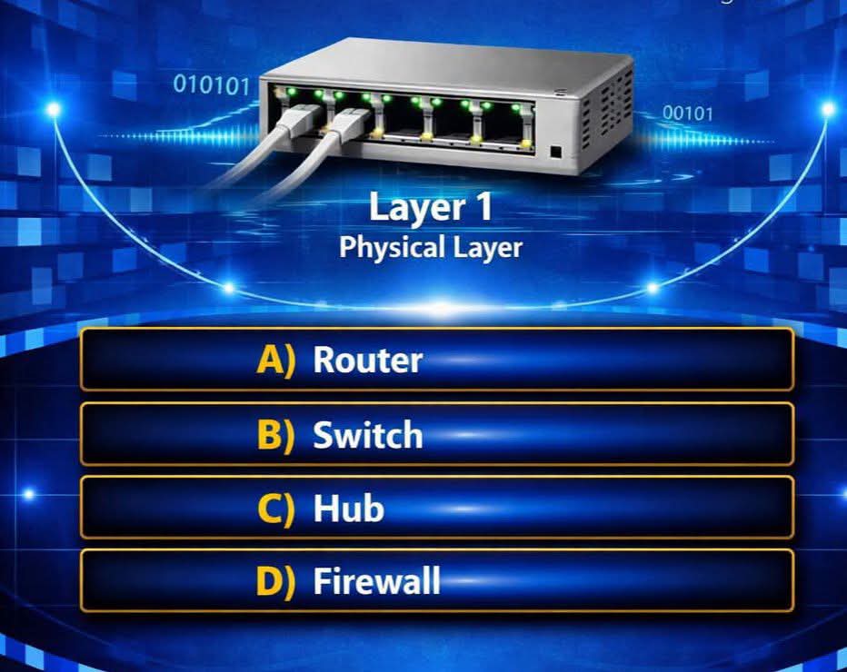
Which Networking Device Works at the Physical Layer (Layer 1)?
Question:
Which networking device works at the Physical Layer (Layer 1) of the OSI model?
The correct answer is:
Hub
Introduction
Computer networks are built on a layered architecture that simplifies communication between devices and ensures interoperability among different hardware and software vendors. One of the most widely recognized networking models is the Open Systems Interconnection (OSI) Model, developed by the International Organization for Standardization (ISO). The OSI model divides network communication into seven layers, with each layer performing specific functions.
The Physical Layer, also known as Layer 1, is the lowest layer of the OSI model. It is responsible for transmitting raw binary data (bits) over physical communication media such as copper cables, fiber-optic cables, or wireless radio waves. Unlike higher layers, the Physical Layer does not interpret data or examine addresses; it simply moves electrical, optical, or radio signals from one device to another.
Several networking devices operate at different OSI layers. For example, routers work at Layer 3, switches generally work at Layer 2, and firewalls can operate at multiple layers. The networking device traditionally associated with the Physical Layer is the Hub because it simply receives electrical signals and repeats them to all connected ports without performing any data processing or address filtering.
Understanding the OSI Model
The OSI model consists of seven layers:
- Physical Layer
- Data Link Layer
- Network Layer
- Transport Layer
- Session Layer
- Presentation Layer
- Application Layer
Each layer has unique responsibilities.
The Physical Layer forms the foundation of all network communication.
What Is the Physical Layer?
The Physical Layer (Layer 1) is responsible for transmitting and receiving raw bits over the communication medium.
Its functions include:
- Bit transmission
- Electrical signaling
- Optical signaling
- Radio signal transmission
- Cable specifications
- Connector standards
- Signal timing
- Data encoding
- Physical topology
- Transmission media selection
Layer 1 is concerned only with moving bits from one location to another.
It does not understand:
- MAC addresses
- IP addresses
- Packets
- Frames
- Protocols
Its responsibility is simply to transport binary information.
What Is a Hub?
A Hub is a basic networking device that operates entirely at the Physical Layer (Layer 1).
Its primary function is to receive incoming electrical signals from one port and immediately repeat those signals to every other connected port.
A hub performs no intelligent processing.
It does not:
- Read destination addresses
- Filter traffic
- Learn device locations
- Make forwarding decisions
Instead, every signal entering a hub is broadcast to all connected devices.
How a Hub Works
Imagine four computers connected to a hub.
If Computer A sends data, the hub receives the electrical signal.
Rather than determining which computer should receive the information, the hub copies the signal and transmits it to:
- Computer B
- Computer C
- Computer D
Every connected device receives the same signal.
Only the intended recipient processes the data, while the others simply ignore it.
This broadcasting behavior is why hubs are considered simple repeaters.
Characteristics of a Hub
A hub has several defining characteristics.
Operates at Layer 1
A hub functions exclusively at the Physical Layer.
It handles only electrical or optical signals.
No Address Learning
Unlike switches, hubs do not maintain MAC address tables.
They cannot identify where devices are connected.
Broadcasts All Traffic
Every incoming signal is repeated to every port.
This increases unnecessary network traffic.
Shared Bandwidth
All connected devices share the available bandwidth.
If one device uses a significant portion of the bandwidth, less remains available for others.
Single Collision Domain
Because every device shares the same communication medium, collisions can occur when multiple devices transmit simultaneously.
Older Ethernet networks relied on CSMA/CD (Carrier Sense Multiple Access with Collision Detection) to manage these collisions.
Functions of the Physical Layer
The Physical Layer performs several important tasks.
Bit Transmission
It transfers binary digits (0s and 1s) across communication channels.
Signal Conversion
It converts digital bits into:
- Electrical signals
- Optical light pulses
- Radio frequency waves
depending on the transmission medium.
Data Rate Definition
Layer 1 specifies transmission speeds such as:
- 10 Mbps
- 100 Mbps
- 1 Gbps
- 10 Gbps
- 100 Gbps
Connector Standards
Examples include:
- RJ45
- LC
- SC
- ST
- USB
- Coaxial connectors
Cable Specifications
Physical Layer standards define:
- Cable length
- Cable type
- Shielding
- Pin assignments
Physical Topology
The Physical Layer supports different layouts including:
- Bus
- Star
- Ring
- Mesh
Examples of Physical Layer Devices
Several devices operate primarily at Layer 1.
Hub
The most common Layer 1 networking device.
Repeats signals to every connected port.
Repeater
A repeater regenerates weak electrical or optical signals.
Its purpose is to extend communication distance.
It does not inspect transmitted data.
Media Converter
Media converters translate between different transmission media.
Examples include:
- Copper to fiber
- Fiber to copper
They operate at Layer 1 because they simply convert signal formats.
Network Cables
Physical transmission media are considered Layer 1 components.
Examples include:
- Twisted pair cable
- Coaxial cable
- Fiber-optic cable
Connectors
Examples include:
- RJ45
- LC
- SC
- ST
These connectors physically attach communication equipment.
Hub vs Switch
Many beginners confuse hubs with switches.
Although both connect multiple devices, they operate differently.
Hub
- Layer 1
- Broadcasts all traffic
- No MAC address table
- Shared bandwidth
- More collisions
- Lower efficiency
Switch
- Layer 2
- Learns MAC addresses
- Sends frames only to the correct destination
- Dedicated bandwidth per port
- Few or no collisions
- Higher performance
Modern Ethernet networks almost always use switches instead of hubs.
Why Hubs Are Rare Today
Hubs have become largely obsolete because of several disadvantages.
Poor Performance
Broadcasting every frame wastes bandwidth.
Security Risks
All devices receive all transmitted traffic.
Malicious users can capture network packets more easily.
Collision Problems
As more devices communicate, collisions increase significantly.
Low Efficiency
Bandwidth is shared among all connected devices.
No Traffic Management
Hubs cannot prioritize, filter, or optimize network traffic.
For these reasons, switches replaced hubs in nearly all modern networks.
Practical Example
Imagine a classroom containing six computers connected through a hub.
Student A sends a file to Student C.
The hub receives the electrical signal.
Instead of forwarding it only to Student C, the hub sends identical copies to:
- Student B
- Student C
- Student D
- Student E
- Student F
Only Student C accepts the frame.
Every other computer discards it.
This unnecessary broadcasting consumes bandwidth and reduces overall network efficiency.
Physical Layer in Telecommunications
The Physical Layer is equally important in telecommunications.
Examples include:
- Fiber-optic transmission
- Microwave links
- Cellular radio systems
- Satellite communication
- Ethernet cables
- Optical modules (SFPs)
- RF antennas
Telecommunication engineers regularly work with Layer 1 technologies when installing, testing, and maintaining network infrastructure.
Modern Layer 1 Technologies
Today’s Physical Layer includes many advanced technologies.
Examples include:
- Gigabit Ethernet
- 10 Gigabit Ethernet
- Fiber Channel
- DWDM optical transmission
- Passive Optical Networks (PON)
- Microwave backhaul
- 5G radio interfaces
- Industrial Ethernet
Although these technologies are much more sophisticated than traditional hubs, they still perform the fundamental Layer 1 function of transmitting raw bits.
Troubleshooting Physical Layer Issues
Network engineers often begin troubleshooting at Layer 1 because physical problems can affect all higher layers.
Common Layer 1 issues include:
- Broken cables
- Loose connectors
- Fiber bends
- Damaged ports
- Power failures
- Incorrect cable types
- Signal attenuation
- Electromagnetic interference
- Faulty transceivers
Typical troubleshooting tools include:
- Cable testers
- Multimeters
- Optical power meters
- OTDR (Optical Time Domain Reflectometer)
- Network analyzers
Resolving Physical Layer issues often restores normal network operation without changes to higher-layer protocols.
Best Practices
To maintain reliable Physical Layer performance:
- Use high-quality network cables.
- Follow cable length specifications.
- Protect cables from physical damage.
- Label cables and ports clearly.
- Use proper grounding for equipment.
- Avoid excessive cable bending.
- Test new installations thoroughly.
- Replace damaged connectors promptly.
- Maintain clean fiber-optic connectors.
Following these practices improves reliability and reduces downtime.
Conclusion
The correct answer is Hub. A Hub is a networking device that operates at the Physical Layer (Layer 1) of the OSI model because it simply receives incoming electrical signals and repeats them to every connected port without interpreting addresses or making forwarding decisions. The Physical Layer is responsible for transmitting raw bits across communication media, defining electrical and optical signaling, connector standards, cable specifications, and transmission characteristics. Other Layer 1 devices include repeaters, media converters, cables, and connectors, all of which focus on the physical movement of data rather than processing network information. Although hubs have largely been replaced by more intelligent Layer 2 switches due to their inefficiency and security limitations, understanding how hubs function provides a solid foundation for learning computer networking and the OSI model. Knowledge of the Physical Layer is essential for network engineers, telecommunications professionals, and IT specialists because every communication system ultimately depends on reliable physical connectivity to support higher-layer network operations.